ABSTRACT
A fusion reactor concept is described in which a low-beta plasma is supplied with D-T fuel, heating, and inductive energy using high-speed plasma rings injected from both ends into a central chamber. The high plasma current is slowly built up over time using modest injection hardware. The concept appears to be more attractive than current magnetic and inertial fusion approaches.
INTRODUCTION
The
RACE (Ring Acceleration Experiment) machine at LLNL [1], performed in the
1980s, and its successor, MARAUDER [2] were coaxial guns capable of
accelerating dense plasma rings to over 2000 km/sec with injection efficiencies
over 25%. At this velocity, if D-T were used instead of hydrogen, ion
temperatures of up to 50 keV could be achieved after slowing down and
thermalizing. Thermalized electron temperatures, on the other hand, would be
only a few eV. Therefore, unlike ohmic heating, this approach could initially
heat ions directly, which makes more effective use of allowable plasma
pressures when starting up a fusion reactor.
That there is interest in compact torus injection is shown by the number of experiments conducted in the past and recently [3-6]. There have also been some interesting reactor studies as well [7,8]. The purpose of this article is to add some innovations to this body of knowledge.
GENERAL DESCRIPTION
Present
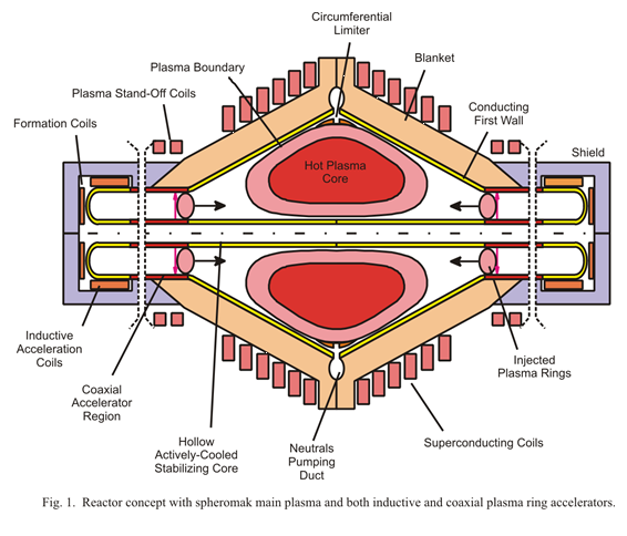
A cross-section of the reactor concept is shown in Fig. 1
above. It is cylindrically symmetric, and the left and right halves can be
slid apart for maintenance access. The plasma is surrounded by conical
conducting first walls and neutron-absorbing blankets. Outside the blanket are
superconducting coils that keep the confining plasma current from expanding
outward. The coil fields are stronger at the ends to keep the current centered
by providing an axial magnetic well. A central passive core, which is hollow,
actively-cooled and electrically conducting, helps stabilize the plasma
vertically. There is no current in that core.
To each side of the main plasma are the injectors. These supply D-T fuel in plasma rings at very high velocity. The embedded currents in these rings merge with the main plasma current and slowly build it up. Inductive acceleration first brings the plasma rings up to a few hundred km/sec. Then the coaxial accelerators take over and bring the rings to about 1600 km/sec.
The injector system requires capacitor banks of several megajoules each for plasma formation and for acceleration. Pulse rates around 20 Hz are needed. Based on results from RFP-type experiments [9], these parameters appear feasible.
THE LOW-BETA MAIN PLASMA
The main plasma could be a spheromak (some toroidal flux) or field-reversed mirror (poloidal flux only). In either case it is low beta (ratio of plasma pressure to magnetic pressure). The result is a very high plasma current (about 60 MA) at the fusion power densities needed. The external coils keep this current, and the plasma, firmly in place, much like toroidal fields that stabilize the plasma in tokamaks.
The plasma sketched in Fig. 1 shows an inner and outer boundary. This is an artifact used in the calculations to approximate density and temperature profiles. The inner hot core is assumed to have uniform density and temperature throughout and is the useful reacting plasma volume. The outer section is taken to have no particles.
Energy confinement in spheromaks has been low, probably because the experiments have been small. It is expected that the large plasma current in this concept will provide better confinement. However, some energy losses may be preferred to none. Fusion ignition may actually be undesirable because then control is lost and a thermal excursion could occur. Instead, it is preferred that some external heating is needed to maintain an optimum plasma temperature (about 13 keV) while not requiring too much recirculating power.
REACTOR PARAMETERS
The reactor concept shown in Fig. 1 is intended to produce 500 MW of electricity for sale. Up to 150 MW(e) is used to start up the reactor. During startup, the power is taken from the grid. It may also be necessary to add power during the steady state burn, depending on plasma transport losses. Then the power is supplied by the plant electric generator. The gross electricity generated could be as high as 650 MW(e). This amounts to 23% recirculating power. Much higher than that would adversely affect plant economics.
The plasma rings fired into the main plasma supply everything needed to keep it going: fuel, heating, and inductive energy. The main plasma is of course resistive, especially at the beginning. In this simple analysis, it is assumed that 99% of the thermal and inductive energy delivered is dissipated as heat. That still leaves one pecent to build up the main plasma.
The end result is a very long startup time, about 11 hours. This is actually advantageous because the superconducting coils, whose fields must follow the poloidal field, take time to charge up, as does starting up the power plant.
The energy used for startup, about 1.7 GW-hr, must be purchased. The cost of this (~$170 K at $0.10/kW-hr) is recoverable in only about 7 hours of selling electricity. After startup, operation is steady state indefinitely.
The reactor parameters are selected by iterating back and forth in the analysis. In addition to the 500 MW(e) for sale, other fixed parameters are poloidal beta, 10%, and average neutron wall loading, about 2 MWn/m2.
The poloidal beta is about half that already achieved [5]. The second requires some discussion: High neutron wall loadings for a given power no doubt produce a smaller reactor. However, this is at the cost of higher magnetic fields, higher heat fluxes and material thermal stresses, more frequent blanket changeouts due to neutron damage, and possibly poorer plasma confinement due to the smaller size. The wall loading used here is comfortable for a reactor plant.
The total thermal power assumes 40% power conversion efficiency and 10% blanket neutron energy multiplication. The result is 1620 MW(th) total and 1200 MW of neutron power. This conversion efficiency is readily achieved with a steam plant having a peak steam temperature of 540°C (1000 °F) and a condensing temperature as high as 66 °C (150 °F). This efficiency is 70% of the ideal Carnot efficiency (about the same as existing plants). The high condensing temperature could allow plant siting in remote areas where cooling water is scarce.
A reasonable major radius, R, and plasma radius out to the limiter, a, is chosen: R = 4 m and a = 2.67 m. That gives an aspect ratio R/a = 1.5, which is common for spheromaks and allows room for a central stabilizing core. Taking the useful hot first wall area to be out to the injectors and limiter, and using a 30° cone angle, that area is 575 m2. This gives an average neutron wall loading of 2.1 MWn/m2, as desired.
There is the question of the proper cone angle. The one chosen gives a prolate plasma, which might be tilt unstable. It is hoped that the central core will provide some stability. Recent experiments, however, have shown the prolate shape to be stable after magnetic reconnection [6].
Plasma density and temperature profiles are unknown at this point. However, because everything enters the edge of the plasma, one would expect reasonably flat density, temperature, and current density profiles. In this analysis, actual expected profiles are approximated by flat out to 0.6a with density and temperature values equal to that on axis. Outside of 0.6a all values are taken to be zero. This gives a useful reacting plasma volume of 257 m3. The neutron power density is then 1200 MWn/257 m3 = 4.7 MWn/m3.
As mentioned above, it is assumed that the steady state burn could be slightly subignited so that the injectors can be used to control plasma temperature. The optimum temperature, where <sV>/T2 is maximized, is 13.6 keV for D-T. The term <sV> is the fusion cross section at that temperature in m3/sec. Dividing it by T2 represents the fusion power density for a given plasma pressure in the 10-20 keV temperature range. Running at the best <sV>/T2 is significant because all of the investment is going into creating this pressure.
In this analysis, it is assumed that Ti = Te and plasma densities ni = ne. However, the injectors provide high values of Ti after thermalization at the edge of the plasma with negligible Te, while ohmic heating heats electrons in the center. Therefore, in reality, only detailed analysis will show the actual temperature profiles over time.
The plasma pressure at the temperatures above is 0.88 MPa. The corresponding plasma density for the power density above is ni = 2´1020 m-3. With 10% beta, the confining pressure from the plasma current is 8.8 MPa.
This gives a plasma current of 63 MA and a poloidal field at the plasma edge of 4.7 T. This is the field that must be supplied by the superconducting coils at the limiter. The fields at the end coils are higher. At the moment, they are taken to 7.0 T, a little below the maximum for NbTi superconductors.
The center and edge coil radial thicknesses are 1.2 m and 1.0 m, respectively, giving average hoop stresses for each of about 63 MPA (9 ksi). It is important for the sake of reliability to have moderate stresses like these in superconducting coils because they are difficult to repair, and failure can be catastrophic.
Repeating a key point: The high plasma current is not a major concern because the hardware needed to create it is modest. Rather than one swing of a large ohmic heating coil, many plasma rings with internal currents are rapidly injected to achieve that current. And even though the current is large, the magnetic fields needed to contain it are within the scope of existing superconducting technology. In addition, those superconducting coils are simple non-interlocking circular solenoids.
PLASMA CONFINEMENT TIME
At steady fusion burn, the alpha power is 300 MW. This is entirely absorbed into the plasma and then migrates out of it. Losses are Bremmstrahlung radiation, 61 MW, and alpha power transport through particle conduction, convection, and charge exchange.
In steady state, this transport is the difference between these two, 239 MW, if there is no heating from the injected plasma rings. In that case, a global energy confinement time at steady state of te = 0.8 sec is needed, which is not unreasonable.
INJECTORS
The coaxial injectors are taken to be 10 m long, somewhat longer than the 6 m in the RACE experiment. This gives an average accelerating force on the plasma rings, 70 kN, equal to the inductive force holding the plasma ring together, taken to be Emag/(2aring). This acceleration, about 1010-g's, has shown to be acceptable by experiment [2]. The outer and inner electrode radii are 1.67 m and 0.55 m respectively.
Stability of the plasma ring is helped during acceleration by the fact that the electrodes have some electrical resistance. Should a part of the plasma try to advance ahead of the rest, the local accelerating current would reduce due to that longer, and more resistive, section of the electrode.
The plasma ring poloidal beta is taken to be 20%, twice the main plasma. The argument is that, under acceleration, it is confined and cannot go anywhere except down the tube. Ring plasma ion density is taken to be 2´1019 m-3, lower than in the RACE experiment.
Plasma temperature during acceleration is assumed to be 100 eV. At the 20% beta, this requires a ring plasma current of 0.25 MA. The resulting inductive energy per ring is 77 kJ. Taking the RACE injection efficiency of 25%, the 150 MW(e) of peak recirculating power delivers 37 MW of injected power. The total energy injected (thermal + inductive + kinetic) per ring pair (i.e., both sides) is 1.6 MJ.
With that 37 MW of total power injected, the pulse rate is 23 Hz. The total energy in the main plasma (inductive + thermal) once it reaches steady burn is 15 GJ. Assuming only one percent of the injected energy is used to build up the current, and the rest goes to heat, then at least 940,000 pulses are needed to reach steady state current and density. This takes about 11 hours.
MERGING OF PLASMA RINGS INTO MAIN PLASMA
It is assumed that the plasma rings will merge into the main plasma and not bounce back or blow past each other. This has been shown experimentally in the T-3 and SSX machines for moderate plasma ring velocities [3,5]. Magnetic reconnection and relaxation of the main plasma dissipates some of the injected magnetic energy into heat [4].
No information has been found regarding merging of spheromaks at very high-velocities. However, there is an attractive force between rings and the main plasma current (Remember that all currents are in the same direction). In addition, once the plasma rings reach the main plasma, collisions will occur between the two and it is expected that this will also accommodate merging.
LIMITER
Because of the injection ports at both ends, divertors there do not appear feasible. Instead, a large circumferential limiter is used to define the plasma boundary. The heat load on this limiter is made up of particle transport, Bremmstrahlung radiation and some neutron heating.
The limiter would be divided into many panels. Only one set would be fixed. The others would articulate radially by means of bimetallic strips, depending on their temperature, so as to evenly distribute the heating.
The limiter material needs to be capable of a heat load up to about 1.5 MW/m2 (150 W/cm2). However, it does not have to be at high temperature. Even 300°C is sufficient to make use of this heat. In fact, all the plasma facing components can be at this modest temperature and still get 40% conversion to electricity. For example, that heat can be used to preheat feedwater in a steam power conversion system, eliminating the need for steam extractions from the turbine stages.
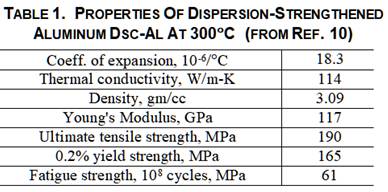
There are new materials coming available that could be used for the limiter. A very interesting one is DSC-Al, developed for diesel engine pistons [10], which are subjected to heat loads reaching 5 MW/m2. The material is made up of pure aluminum interspersed with 35% aluminum oxide nanoparticles.
Table 1 gives some mechanical and thermal properties of DSC-Al at 300°C. There are other dispersion-strengthened materials, for example using iron nanoparticles, that are also interesting. Similar dispersion-strengthened materials have been considered in the past. However these new materials use nanometer-sized particles and appear capable of large scale production at reasonable cost.
No information is available about damage in DSC-Al from energetic neutrons. However, the material has very fine microstructure, which could be helpful. Also, with irradiation occurring at fairly high temperature, in-situ annealing may occur. At any rate, the limiters are accessible for replacement.
Similarly, sputtering of this material by energetic plasma particles is unknown. Again though, the fine microstructure and high alumina fraction may help, as might the cloud of thermalized neutral particles surrounding the limiter. But an issue could be charge-exchange between energetic ions and cool neutrals, which can enter the hot plasma.
THE IMPURITY ISSUE IN THE INJECTORS
An issue with the RACE experiment was mass build up in the plasma due to sputtering of the electrodes from the plasma ring itself [11]. The mass buildup seems to occur because particles in the plasma rings have very high axial momentum but little radial momentum. The resultant momentum vector is at a glancing incidence to the electrode wall. Sputtering from such shallow angles is especially severe [12], and is akin to chiseling away of the surface.
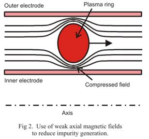
An attempt at reducing sputtering could be the following: Plasma stand-off coils shown in Fig. 1 would supply a weak axial magnetic field that is compressed between the electrically-conducting electrodes and the high-speed electrically-conducting plasma rings, as suggested in Fig. 2 below.
This hopefully should keep the energetic plasma particles off the walls of the electrodes. The magnitude of this field needs to be determined, probably by experiment, as well as its interaction with other fields. This field compression works best at the higher speeds, where it is needed the most.
Note that the accelerating current, which uses electrons not ions, creates few impurities. Low-Z coatings on the electrodes may still be needed, however. Boron might be attractive: It is low-Z and electrically conducts at high temperature.
ADDING DYNAMIC COMPRESSION
A modification to the geometry shown in Fig. 1 might be having the plasma rings go into converging cones before reaching the main chamber. This would slow and compress the rings, increasing both ion and electron temperatures, thereby reducing the resistivity in the main current. It might also assure that the plasma rings do in fact merge.
SUMMARY
This article has been written to offer a more attractive approach to nuclear fusion power plants. If the currently dominant confinement methods, tokamaks, stellarators, and laser inertial fusion, showed promise of commercial viability, this task would be superfluous. But this seems to be not the case.
The RACER concept is attractive for power reactors because it is or has:
· Cylindrically symmetric
· Maintainable
· Steady state
· Moderate-field circular superconducting coils
· High plasma current built up using moderate hardware
· Fuel, heating and inductive energy supplied by very high-speed plasma rings
· Moderate neutron wall loading
· Low beta with resulting better confinement and stability
· Moderate recirculating power
· Some basis in experimental results
While the reactor parameters are given throughout the body of this article, for convenience they are also summarized in Table 2 below.
TABLE 2. SUMMARY OF REACTOR PARAMETERS
| Electricity for sale | 500 MW(e) |
| Recirculating power | up to 150 MW(e) |
| Poloidal beta | 10% |
| Neutron wall loading | 2.1 MWn/m2 |
| Major radius | 4 m |
| Plasma radius to wall | 2.67 m |
| Aspect ratio | 1.5 |
| First wall cone angle | 30° |
| Reactor OD to outside of coils | 19.5 m |
| Reactor length up to injector channels | 18.4 m |
| Reactor total length | 48 m |
| Electrical power conversion efficiency | 40% |
| Blanket neutron energy multiplication | 1.1 |
| Total thermal power | 1620 MW |
| Neutron power | 1200 MW |
| Alpha power | 300 MW |
| Optimum main plasma temperature | 13.6 keV |
| Ave density ni and ne each | 2x10²⁰ m-3 |
| Bremsstrahlung power | 61 MW |
| Assumed Zeff | 3 |
| Required energy confinement time | 0.8 sec |
| with no auxiliary heating |
|
| Limiter surface area | 175 m2 |
| Limiter heat flux | 1.5 MW/m2 |
| B field at midplane | 4.7 T |
| B field at ends | ~7 T |
| Center S/C coil radial thickness | 1.2 m |
| End S/C coil radial thickness | 1.0 m |
| Average hoop stress all coils | 63 Mpa (9 ksi) |
| Inductive accelerator length | 3 m (est.) |
| Coaxial accelerator length | 10.5 m |
| Outer electrode radius | 1.67 m |
| Inner electrode radius | 0.55 m |
| Plasma ring major radius | 1.11 m |
| Plasma ring plasma radius | .56 m |
| Max injection velocity | 1600 km/sec |
| Plasma ring max acceleration | 1.2x10¹⁰ g's |
| Max injection rateup to | 23 HZ |
| Time to startup with 99% losses | 11.4 hrs |
| Min injection pulses during startup | 940,000 |
| Total purchased energy for startup | 1.7 GW-hr |
SUGGESTED FUTURE WORK
If there is further interest in this concept, future analytical work could include detailed magnetics analyses including steps along the ramp-up to steady burn, including a time-dependent analysis of the plasma power balance. This was done in the past [7], but an assumed energy confinement scaling law was used.
One approach would be to perform a very slow ramp-up, determine what energy confinement is needed to keep plasma temperature climbing, and then compare that with possible confinement scaling laws. This could establish the actual ring inductive energy that remains after merging.
If the above tasks continue to show promise, possible experiments could include (1) use of weak magnetic fields to limit impurities in a coaxial accelerator and (2) a small version of the configuration shown in Fig. 1 to learn about magnetic reconnection and merging at high plasma ring velocities, the use of the prolate geometry, and the need for a central conducting core.
ACKNOWLEDGMENTS
This work would not have been possible without the expert help in physics and magnetics from Michael Schaffer and Paul Parks (who suggested the original concept), both of General Atomics.
REFERENCES
1. J. H. Hammer, C. W. Hartman, J. L. Eddleman and H. S. McLean, "Experimental demonstration of acceleration and focusing of magnetically confined plasma rings", Phys. Rev. Letters, Vol. 61, No. 25, pp. 2843-2846, 19 Dec 1988.
2. J. H. Degman, R. E. Peterkin, G. P. Baca, J. D. Beason, D. E. Bell, M. E. Dearborn et al, "Compact toroid formation, compression, and acceleration", Phys. Fluids, Vol. 5, No. 8, pp. 2938-2958, (Aug 1993).
3. Y. Ono, M. Inomoto, Y. Ueda, T. Matsuyama, and T. Okazaki, "New relaxation of merging spheromaks to a field reversed configuration". Nuclear Fusion Vol. 38, No. 11Y, pp. 2001-2008, Nov 1999.
4. T. Gray, V. S. Lukin, M. R. Brown, and C. D. Cothran, "Three-dimensional reconnection and relaxation of merging spheromak plasmas", Physics of Plasmas, 17, 102106 (2010).
5. T. Gray, M. R. Brown, C. D. Cothran, G. Marklin, and M. J. Schaffer, "Stable spheromak formation by merging in an oblate flux conserver:", Physics of Plasmas, 17, 032510 (2010).
6. M. R. Brown, C. D. Cothran, J. Fung, M. Chang, J. Horwitz, M. J. Schaffer, J. Leuer, and E. V. Belova, "Dipole trapped spheromak in a prolate flux conserver", Physics of Plasmas, 13, 102503 (2006).
7. R. F. Bourque, "The colliding compact torus: A steady state fusion reactor with pulsed heating, fueling, and current drive", J. Fusion Energy, Vol. 17, No. 3, pp. 207-208, (1998).
8. T. K. Fowler, D. D. Hua, E. B. Hooker, R. W. Moir, and L. D. Pearlstein, "Pulsed spheromak fusion reactors", Lawrence Livermore National Laboratory Report UCRL-JC-132109, (1998).
9. M. J. Schaffer, General Atomics, personal communication, (c. 1990).
10. AMT Advanced Material Technology, URL: http://amt-advanced-materials-technology.com/materials/aluminum-high-temperature/.
11. T. K. Fowler, LLNL (retired), personal communication, (July 17, 1996).
12. T. Ono, M. Ono, K. Shibata, T. Kenmotsu, Z. Li, and T. Kawamura, " Calculation of sputtering yield with obliquely incident light-ions (H+, D+, T+, He+) and its representation by an extended semi-empirical formula", URL: www.nifs.ac.jp/report/NIFS-DATA-114.pdf.
File: RACER WEB4.DOC